What Is
Thermal Imaging?
Updated August 2026
Learn how thermal imaging works and how infrared cameras help assess electrical and mechanical equipment
Understanding Thermal Imaging
Thermal imaging, also known as infrared thermography, is a non-contact inspection method used to measure and visualise surface-temperature patterns. A standard camera records visible light reflected from an object. A thermal camera instead responds to infrared radiation, a form of electromagnetic energy that the human eye cannot see.
Infrared forms part of the electromagnetic spectrum. Visible light covers wavelengths of approximately 0.38–0.70 micrometres (µm), while infrared begins just beyond the red end of visible light at longer wavelengths. Industrial thermal cameras used for electrical and mechanical inspections commonly detect long-wave infrared energy within approximately the 7.5–14 µm band.
Every object above absolute zero emits electromagnetic radiation. At the temperatures normally encountered in switchboards, machinery and buildings, much of this emitted energy is within the infrared range. As a surface becomes warmer or cooler, the amount and distribution of infrared energy reaching the camera changes.
The camera converts these differences into a thermal image, known as a thermogram. A selected colour palette makes temperature patterns easier to compare, helping locate areas that differ from similar components or expected operating conditions.
Because the thermal scan is non-contact, multiple electrical and mechanical assets can be assessed efficiently while operating, with minimal disruption to normal operations.
How Does a Thermal Camera Work?
A specialised infrared lens focuses incoming long-wave infrared energy onto a detector array. Unlike the sensor in a standard digital camera, this detector responds to infrared wavelengths rather than visible light.
Most handheld industrial thermal cameras use an uncooled detector called a microbolometer. It contains thousands of individual sensing elements, or pixels. Infrared energy slightly changes the temperature and electrical resistance of each detector element, producing signals that the camera can process.
Using its internal calibration and measurement settings, including emissivity, reflected apparent temperature and distance, the camera calculates an apparent temperature for the visible surface represented by each pixel. The resulting radiometric image contains temperature information for every pixel, rather than being only a coloured photograph, allowing temperatures at individual points or areas to be examined and compared.
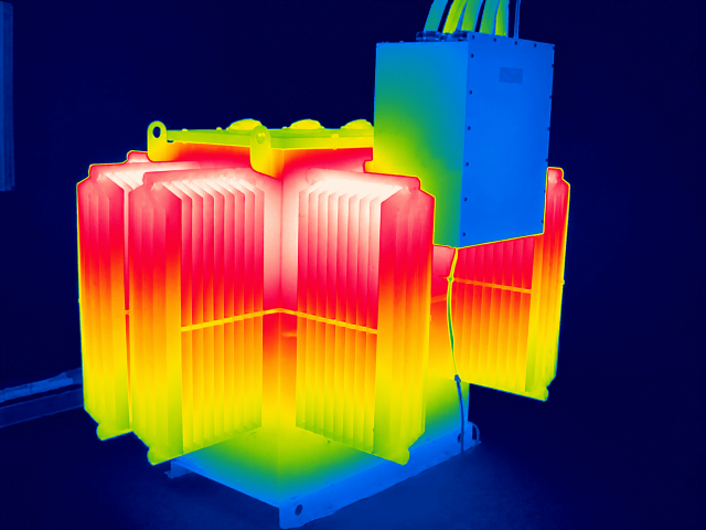
The camera assigns colours to different temperatures. Depending on the selected palette, warmer areas may appear white, yellow, orange or red, while cooler areas may appear purple, blue or black. Changing the palette or displayed temperature range can make a pattern easier to see, but it does not change the underlying radiometric data.
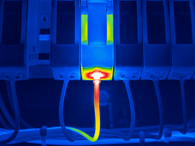
The most useful information is usually the temperature pattern and how it compares with similar components operating under similar conditions. For example, a deteriorated electrical connection may produce localised heating as current flows through it, while friction or inadequate lubrication may cause a bearing to run warmer than comparable bearings.
A thermal image can therefore show where abnormal heating or cooling may be occurring. The pattern must still be considered alongside the equipment type, operating conditions and visual observations before its significance can be determined.
What Can Thermal Imaging Identify?
Thermal imaging is most useful when an issue changes the way heat is generated, transferred or removed. It does not prove the cause of a fault on its own, but it can quickly show where a temperature pattern differs from comparable equipment and where closer investigation should begin.
Electrical Overheating
Electrical thermal imaging can reveal localised heating associated with loose or deteriorated connections, overloaded conductors, faulty circuit breakers, contactors and fuse gear, phase imbalance, and poor cable terminations.
These problems often produce heat because electrical resistance or current is higher than expected. Inspections are therefore completed while equipment is operating under meaningful load, where practicable. Comparing phases and similar components helps distinguish an abnormal pattern from normal operating heat.
Mechanical Issues
Mechanical thermal imaging can reveal abnormal heating associated with excessive friction, inadequate lubrication, misalignment, worn bearings, slipping belts, and restricted movement in motors, gearboxes, conveyors, and other rotating equipment.
A developing issue may appear as a localised hot bearing, an uneven coupling temperature, or one component running warmer than comparable equipment. Comparing similar assets or trending the same asset over time can help show whether its thermal condition is changing.
Cooling & Heat Transfer
Thermal imaging can show where heat is not being removed or transferred as expected. Examples include blocked ventilation paths, dirty filters, failed cooling fans, restricted airflow, fouled heat-exchanger surfaces, and uneven cooling across electrical cabinets or process equipment.
It can also reveal unexpected heat loss, damaged insulation, or uneven temperature distribution. These patterns can help direct checks of airflow, cooling systems, and insulation without assuming that every warm or cool area is a fault.
Thermal Imaging Limitations and Interpretation
A thermal camera does not provide X-ray vision. It detects infrared energy from surfaces within its line of sight and generally cannot see through switchboard covers, machinery guards, enclosures or other solid materials.
A concealed issue may still alter the temperature of a visible surface, but the camera is not seeing through the material. Components that remain hidden behind covers or barriers cannot be assessed directly. Thermal imaging also cannot reveal every electrical or mechanical fault or replace electrical testing, vibration analysis, ultrasound or other diagnostic methods where required.
Some faults generate little or no heat, occur only intermittently or do not produce a sufficient surface-temperature difference under the conditions present during the inspection. Thermal findings therefore reflect equipment load, operating conditions and accessibility at the time.
Capturing a thermal image is relatively straightforward, but interpreting it correctly is where training and experience matter. A warm or bright area is not automatically a fault. Apparent temperature measurements can be affected by surface material, emissivity, reflected infrared energy, viewing angle, distance and camera settings. The observed thermal pattern can also change with weather, sunlight, airflow, nearby heat sources and equipment load.
Accurate interpretation requires appropriate camera settings and an understanding of the surface and inspection conditions. An experienced thermographer considers these factors alongside the equipment type, comparable components, visual observations and site history before determining whether a pattern is significant.
Thermal imaging is best described as a non-contact and minimally disruptive diagnostic tool. It can identify areas requiring further investigation, but it does not replace other inspection or testing methods where these are needed.
Need Thermal Imaging Services in Auckland?
I provide electrical and mechanical thermal imaging inspections, along with AS/NZS 3019 periodic assessments, across Auckland and throughout New Zealand.
Auckland Thermography Ltd
021 139 2360
22/18 Hewlett Rd, Massey, Auckland 0614
Hours & locations
Monday - Friday: 6am - 5pm
Auckland based - inspections can be carried out NZ wide and overseas by request